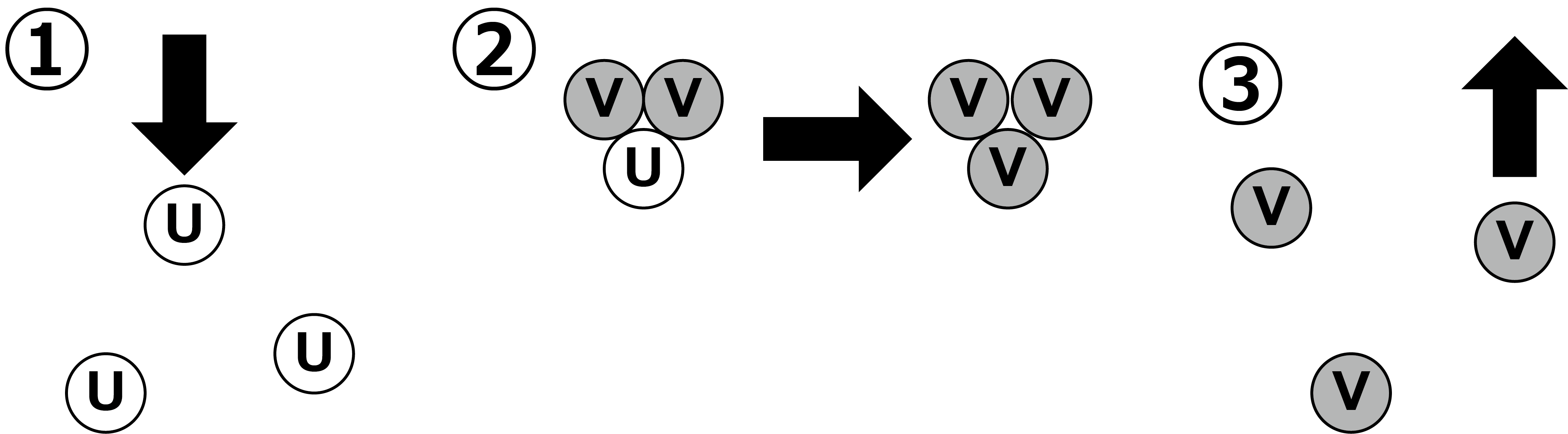
Figure 5.1: Schematic diagram of the "Reaction" of the Gray-Scott model
In nature, there are various patterns such as horizontal stripes of tropical fish and wrinkles like a maze of coral. The genius mathematician Alan Turing expressed the occurrence of these patterns that exist in nature with mathematical formulas. The pattern generated by the mathematical formulas he derived is called the "Turing pattern". This equation is commonly referred to as the reaction-diffusion equation. Based on this reaction-diffusion equation, we will develop a program to create a picture like a pattern of a living thing using Compute Shader on Unity. At first, we will create a program that operates on a two-dimensional plane, but at the end, we will also introduce a program that operates on a three-dimensional space. For details on ComputeShader, refer to "Chapter 2 Introduction to ComputeShader" in UnityGraphicsProgramming vol.1.
The sample in this chapter is "Reaction Diffusion" from
https://github.com/IndieVisualLab/UnityGraphicsProgramming3
.
As the name suggests, Reaction Diffusion is a local chemical reaction in which the concentrations of one or more substances distributed in a space change with each other, and space. It is a mathematical model of how diffusion, which spreads throughout the whole, changes due to the influence of two processes. This time, we will use the "Gray-Scott model" as the reaction-diffusion equation. The Gray-Scott model was published in a treatise by P. Gray and SKScott in 1983. Roughly speaking, when two virtual substances, U and V, are filled in the grid, they react with each other to increase or decrease or diffuse, and the concentration in the space changes over time. Various patterns will appear as you go.
Figure 5.1 is a schematic diagram of the “Reaction” of the Gray-Scott model.
Figure 5.1: Schematic diagram of the "Reaction" of the Gray-Scott model
Also, as shown in Figure 5.2 , U and V spread to the adjacent grid at different speeds.
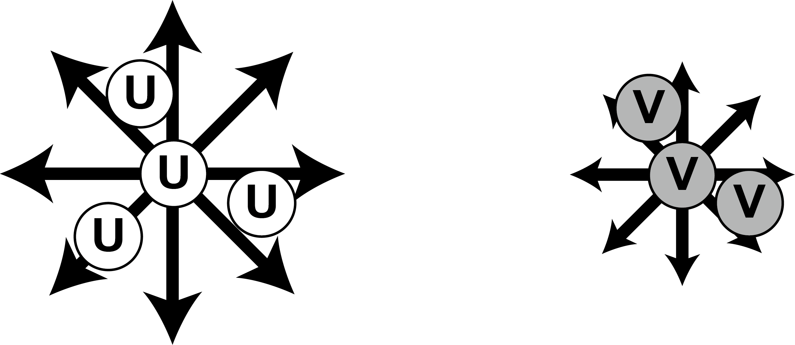
Figure 5.2: Schematic diagram of "Diffusion" in the Gray-Scott model
This difference in diffusion rate creates a difference in U and V concentrations, creating a pattern. The reaction and diffusion of these U and V are expressed by the following equations.
\frac{\partial u}{\partial t} = Du \Delta u - uv^2 + f_{(1-u)}
\frac{\partial v}{\partial t} = Dv \Delta v + uv^2 - (f_{}+k)
In this formula, U is represented by u and V is represented by v . The formula is roughly divided into three.
The first Du \ Delta u and Dv \ Delta v are called the diffusion terms, and the first Du and Dv are constants of the diffusion rate of u and v . The latter half, \ Delta u and \ Delta v, are called Laplacian, and represent the process of diffusion in the direction of eliminating the concentration difference between the surroundings of U and V.
The second is called the reaction term, and uv ^ 2 indicates that U decreases and V increases by reacting with one U and two V.
The third + f_ {(1-u)} is called the inflow term and represents the amount to be replenished (Feed) when U decreases. The closer it is to 0, the more it is replenished, and the closer it is to 1, the more it is replenished. lose. -(f_ {} + k) is called the outflow term, which means that the increased V is reduced by a certain number (Kill).
To summarize a little more simply, U decreases and V increases in response to one U and two Vs. At this rate, U will continue to decrease and V will continue to increase, so U will be replenished by + f_ {(1-u)} and V will be forcibly decreased by- (f_ {} + k). It has become. Then, U and V are diffused to the surroundings by Du \ Delta u and Dv \ Delta v .
Now that I have somehow understood the atmosphere of the equation, I will move on to the explanation of the implementation in Unity. The sample scene whose operation can be confirmed is ReactionDiffusion2D_1 .
Suppose you have U and V density values in a two-dimensional planar grid. This time, we will use Compute Shader to process in parallel, so we will manage the grid with Compute Buffer. First, define the structure in one grid.
ReactionDiffusion2D.cs
public struct RDData
{
    public float u; // U concentration
    public float v; // V concentration
}
ReactionDiffusion2D.cs
/// <summary>
/// Initialization
/// </summary>
void Initialize()
{
    ...

    int wh = texWidth * texHeight; // Buffer size
    buffers = new ComputeBuffer [2]; // Array initialization of ComputeBuffer for double buffering

    for (int i = 0; i < buffers.Length; i++)
    {
        // Grid initialization
        buffers[i] = new ComputeBuffer(wh, Marshal.SizeOf(typeof(RDData)));
    }

    // Grid array for reset
    bufData = new RDData[wh];
    bufData2 = new RDData[wh];

    // Buffer initialization
    ResetBuffer();

    // Initialize the Seed addition buffer
    inputData = new Vector2[inputMax];
    inputIndex = 0;
    inputBuffer = new ComputeBuffer(
        inputMax, Marshal.SizeOf(typeof(Vector2))
      );
}
The buffers of ComputeBuffer for updating are two-dimensional arrays, but there are two for reading and writing. Because the Compute Shader is multi-threaded and processed in parallel. When processing that changes the calculation result by referring to the surrounding grid like this time, if it is one buffer, the calculation result will be referred to the value of the grid that has been calculated earlier depending on the order of the threads to be processed. It will change. In order to prevent it, it is divided into two parts, one for reading and the other for writing.
ReactionDiffusion2D.cs
// Update process
void UpdateBuffer()
{
    cs.SetInt("_TexWidth", texWidth);
    cs.SetInt("_TexHeight", texHeight);
    cs.SetFloat("_DU", du);
    cs.SetFloat("_DV", dv);

    cs.SetFloat("_Feed", feed);
    cs.SetFloat("_K", kill);

    cs.SetBuffer(kernelUpdate, "_BufferRead", buffers[0]);
    cs.SetBuffer(kernelUpdate, "_BufferWrite", buffers[1]);
    cs.Dispatch(kernelUpdate,
      Mathf.CeilToInt((float)texWidth / THREAD_NUM_X),
      Mathf.CeilToInt((float)texHeight / THREAD_NUM_X),
      1);

    SwapBuffer();
}
In the source on the C # side, the parameters that were also in the above equation are passed to the Compute Shader for update processing. Next, the update process in Compute Shader is explained.
ReactionDiffusion2D.compute
// Update process
[numthreads(THREAD_NUM_X, THREAD_NUM_X, 1)]
void Update(uint3 id : SV_DispatchThreadID)
{

  int idx = GetIndex(id.x, id.y);
  float u = _BufferRead[idx].u;
  float v = _BufferRead[idx].v;
  float uvv = u * v * v;
  float f, k;

  f = _Feed;
  k = _K;

  _BufferWrite[idx].u = saturate(
      u + (_DU * LaplaceU(id.x, id.y) - uvv + f * (1.0 - u))
    );
  _BufferWrite[idx].v = saturate(
      v + (_DV * LaplaceV (id.x, id.y) + uvv - (k + f) * v)
    );
}
The calculation is exactly the same as the above equation. GetIndex () is a function for associating 2D grid coordinates with 1D ComputeBuffer index.
ReactionDiffusion2D.compute
// Buffer index calculation
int GetIndex(int x, int y) {
  x = (x < 0) ? x + _TexWidth : x;
  x = (x >= _TexWidth) ? x - _TexWidth : x;

  y = (y <0)? y + _TexHeight: y;
  y = (y> = _TexHeight)? y - _TexHeight: y;

  return y * _TexWidth + x;
}
_BufferRead contains the calculation result one frame before. Extract u and v from there. LaplaceU and LaplaceV are Laplacian functions that collect the U and V concentrations of 8 squares around your grid. This will average the surrounding grid and density. The diagonal grid is adjusted to have a low degree of influence.
ReactionDiffusion2D.compute
// Laplacian function of U
float LaplaceU(int x, int y) {
  float sumU = 0;

  for (int i = 0; i < 9; i++) {
    int2 pos = laplaceIndex[i];
    int idx = GetIndex(x + pos.x, y + pos.y);
    sumU += _BufferRead[idx].u * laplacePower[i];
  }

  return sumU;
}

// Laplacian function of V
float LaplaceV(int x, int y) {
  float sumV = 0;

  for (int i = 0; i < 9; i++) {
    int2 pos = laplaceIndex[i];
    int idx = GetIndex(x + pos.x, y + pos.y);
    sumV += _BufferRead[idx].v * laplacePower[i];
  }

  return sumV;
}
After calculating u and v, write to _BufferWrite. saturate is insurance for clipping between 0 and 1.
By pressing the A key and C key, the function to intentionally add the density difference between U and V to the grid is provided. Press the A key to place SeedNum points (Seeds) at random positions. Press the C key to place one point in the center.
ReactionDiffusion2D.cs
/// <summary>
/// Add Seed
/// </summary>
/// <param name="x"></param>
/// <param name="y"></param>
void AddSeed(int x, int y)
{
  if (inputIndex < inputMax)
  {
    inputData[inputIndex].x = x;
    inputData [inputIndex] .y = y;
    inputIndex++;
  }
}
The inputData array stores the coordinates of the points on the grid.
ReactionDiffusion2D.cs
/// <summary>
/// Pass the Seed array to the Compute Shader
/// </summary>
void AddSeedBuffer()
{
  if (inputIndex > 0)
  {
    inputBuffer.SetData(inputData);
    cs.SetInt("_InputNum", inputIndex);
    cs.SetInt("_TexWidth", texWidth);
    cs.SetInt("_TexHeight", texHeight);
    cs.SetInt("_SeedSize", seedSize);
    cs.SetBuffer(kernelAddSeed, "_InputBufferRead", inputBuffer);
    cs.SetBuffer(kernelAddSeed, "_BufferWrite", buffers[0]);    // update前なので0
    cs.Dispatch(kernelAddSeed,
      Mathf.CeilToInt((float)inputIndex / (float)THREAD_NUM_X),
      1,
      1);
    inputIndex = 0;
  }
}
inputBuffer in, set the inputeData array coordinates entered in the previous point, you pass to ComputeShader.
ReactionDiffusion2D.compute
// Add seed
[numthreads(THREAD_NUM_X, 1, 1)]
void AddSeed(uint id : SV_DispatchThreadID)
{
  if (_InputNum <= id) return;

  int w = _SeedSize;
  int h = _SeedSize;
  float radius = _SeedSize * 0.5;

  int centerX = _InputBufferRead[id].x;
  int centerY = _InputBufferRead[id].y;
  int startX = _InputBufferRead[id].x - w / 2;
  int startY = _InputBufferRead[id].y - h / 2;
  for (int x = 0; x < w; x++)
  {
    for (int y = 0; y < h; y++)
    {
      float dis = distance(
        float2(centerX, centerY),
        float2(startX + x, startY + y)
      );
      if (dis <= radius) {
        _BufferWrite[GetIndex((centerX + x), (centerY + y))].v = 1;
      }
    }
  }
}
The value of v is set to 1 so that it becomes a circle around the coordinates of the inputBuffer passed from C #.
Since the updated grid is just an array, write it to RenderTexture for visualization and make it an image. Write the density difference between u and v in RenderTexture.
First, create a Render Texture. Since the only information to be written to one pixel is the density difference, set RenderTextureFormat to RFloat. RenderTextureFormat.RFloat is a RenderTexture format that can write information for one float per pixel.
ReactionDiffusion2D.cs
/// <summary>
/// Create Render Texture
/// </summary>
/// <param name="width"></param>
/// <param name="height"></param>
/// <returns></returns>
RenderTexture CreateRenderTexture(int width, int height)
{
  RenderTexture tex = new RenderTexture(width, height, 0,
    RenderTextureFormat.RFloat,
    RenderTextureReadWrite.Linear);
  tex.enableRandomWrite = true;
  tex.filterMode = FilterMode.Bilinear;
  tex.wrapMode = TextureWrapMode.Repeat;
  tex.Create();

  return tex;
}
Next, it is the process on the C # side that passes RenderTexture to ComputeShader and writes it.
ReactionDiffusion2D.cs
/// <summary>
/// Write the result of Reaction Diffusion to the texture
/// </summary>
void DrawTexture()
{
  cs.SetInt("_TexWidth", texWidth);
  cs.SetInt("_TexHeight", texHeight);
  cs.SetBuffer(kernelDraw, "_BufferRead", buffers[0]);
  cs.SetTexture(kernelDraw, "_HeightMap", resultTexture);
  cs.Dispatch(kernelDraw,
    Mathf.CeilToInt((float)texWidth / THREAD_NUM_X),
    Mathf.CeilToInt((float)texHeight / THREAD_NUM_X),
    1);
}
This is the processing on the Compute Shader side, the density difference between u and v is obtained from the buffer of the grid and written to the texture.
ReactionDiffusion2D.compute
// Value calculation for texture writing
float GetValue(int x, int y) {
  int idx = GetIndex(x, y);
  float u = _BufferRead[idx].u;
  float v = _BufferRead[idx].v;
  return 1 - clamp(u - v, 0, 1);
}

...

// Draw on texture
[numthreads(THREAD_NUM_X, THREAD_NUM_X, 1)]
void Draw(uint3 id : SV_DispatchThreadID)
{
  float c = GetValue(id.x, id.y);

  // height map
  _HeightMap[id.xy] = c;

}
The normal Unlit Shader is modified and the two colors are interpolated based on the brightness of the texture created in the previous section.
ReactionDiffusion2D.cs
/// <summary>
/// Material update
/// </summary>
void UpdateMaterial()
{
  material.SetTexture("_MainTex", resultTexture);

  material.SetColor("_Color0", bottomColor);
  material.SetColor("_Color1", topColor);
}
ReactionDiffusion2D.shader
fixed4 frag (v2f i) : SV_Target
{
  // sample the texture
  fixed4 col = lerp(_Color0, _Color1, tex2D(_MainTex, i.uv).r);
  return col;
}
When executed, a creature-like pattern should spread on the screen.
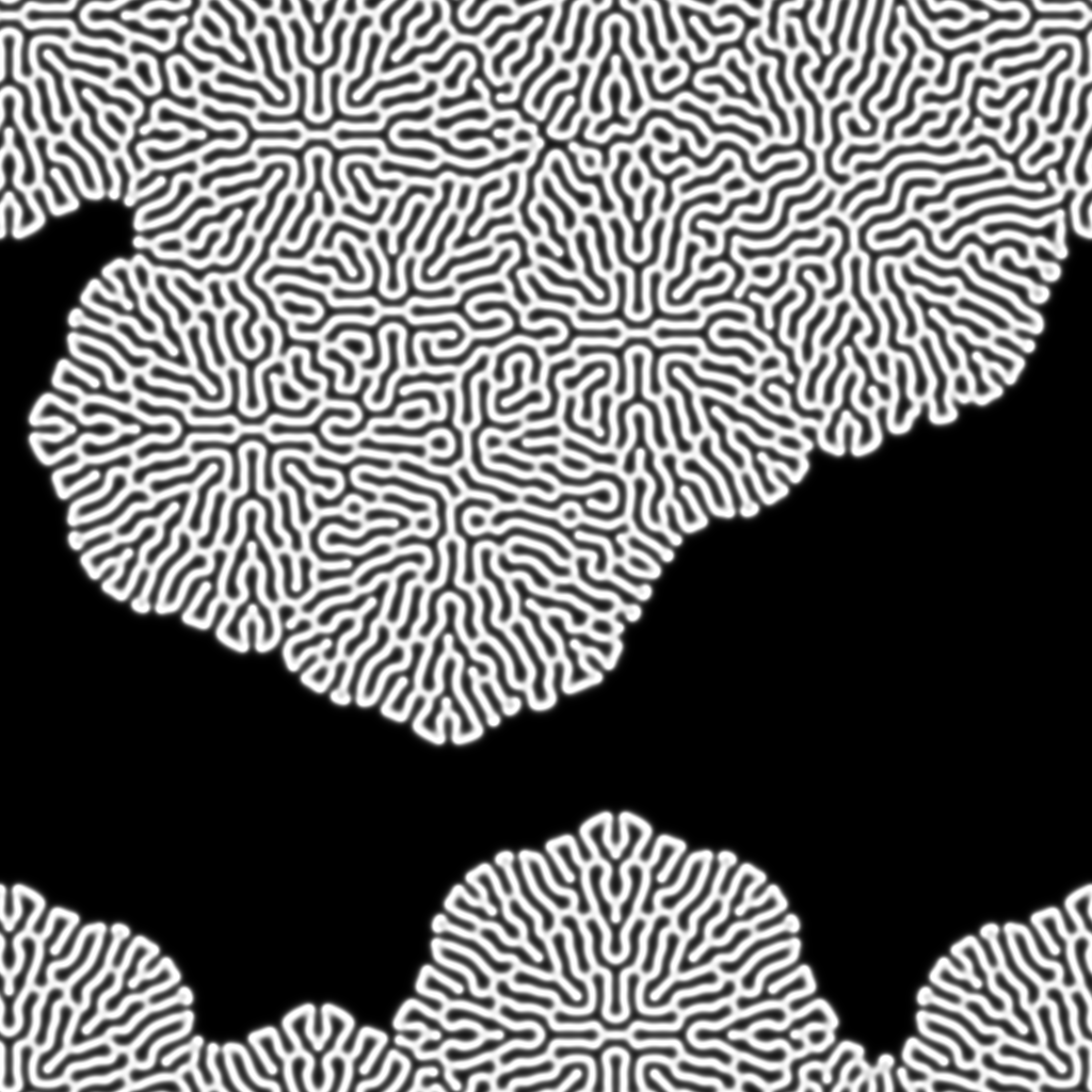
Figure 5.3: Simulation
Just by changing the Feed and Kill parameters a little, various patterns emerge. Here are some parameter combinations.
Feed:0.037 / Kill:0.06
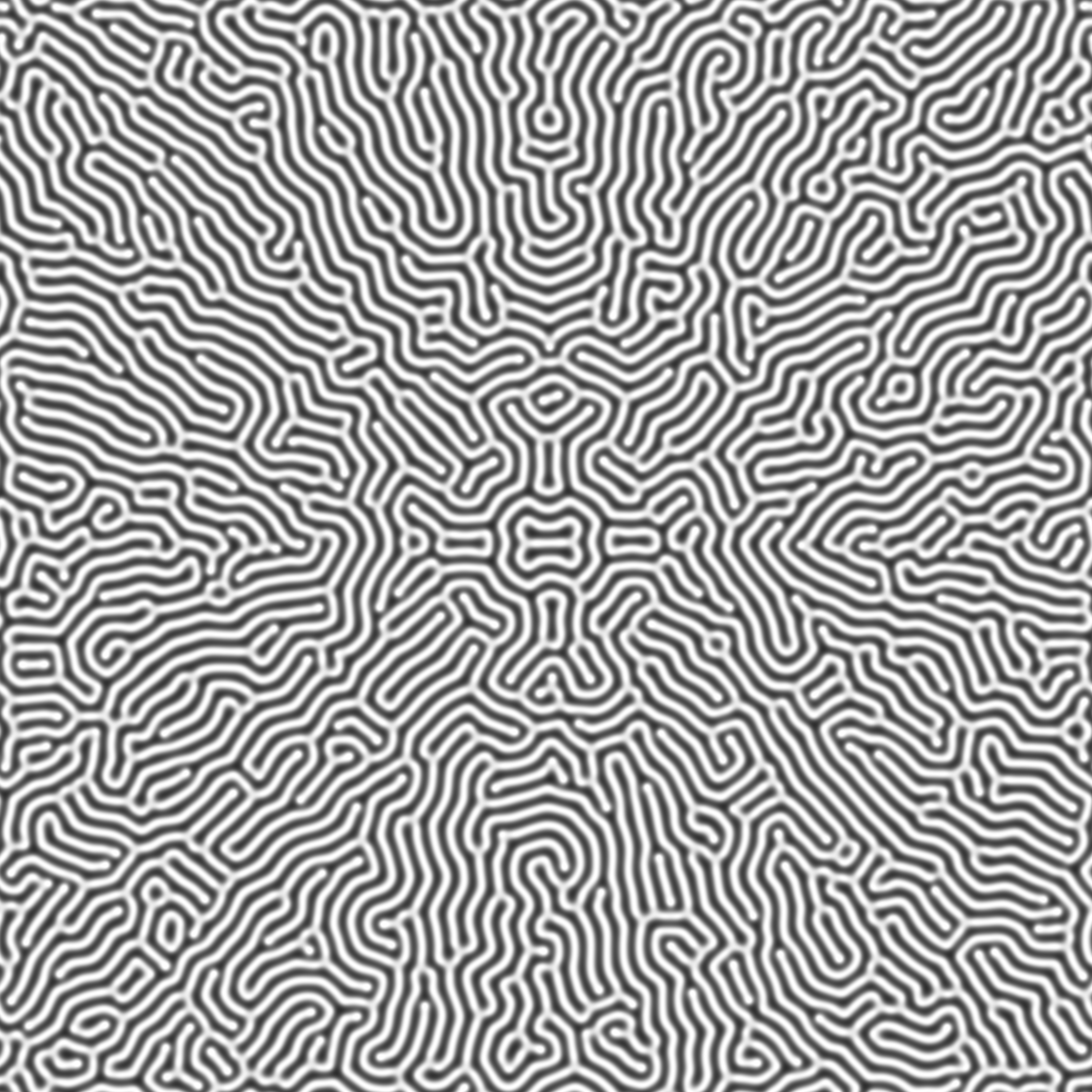
Figure 5.4: Coral-like pattern
Feed:0.03 / Kill:0.062
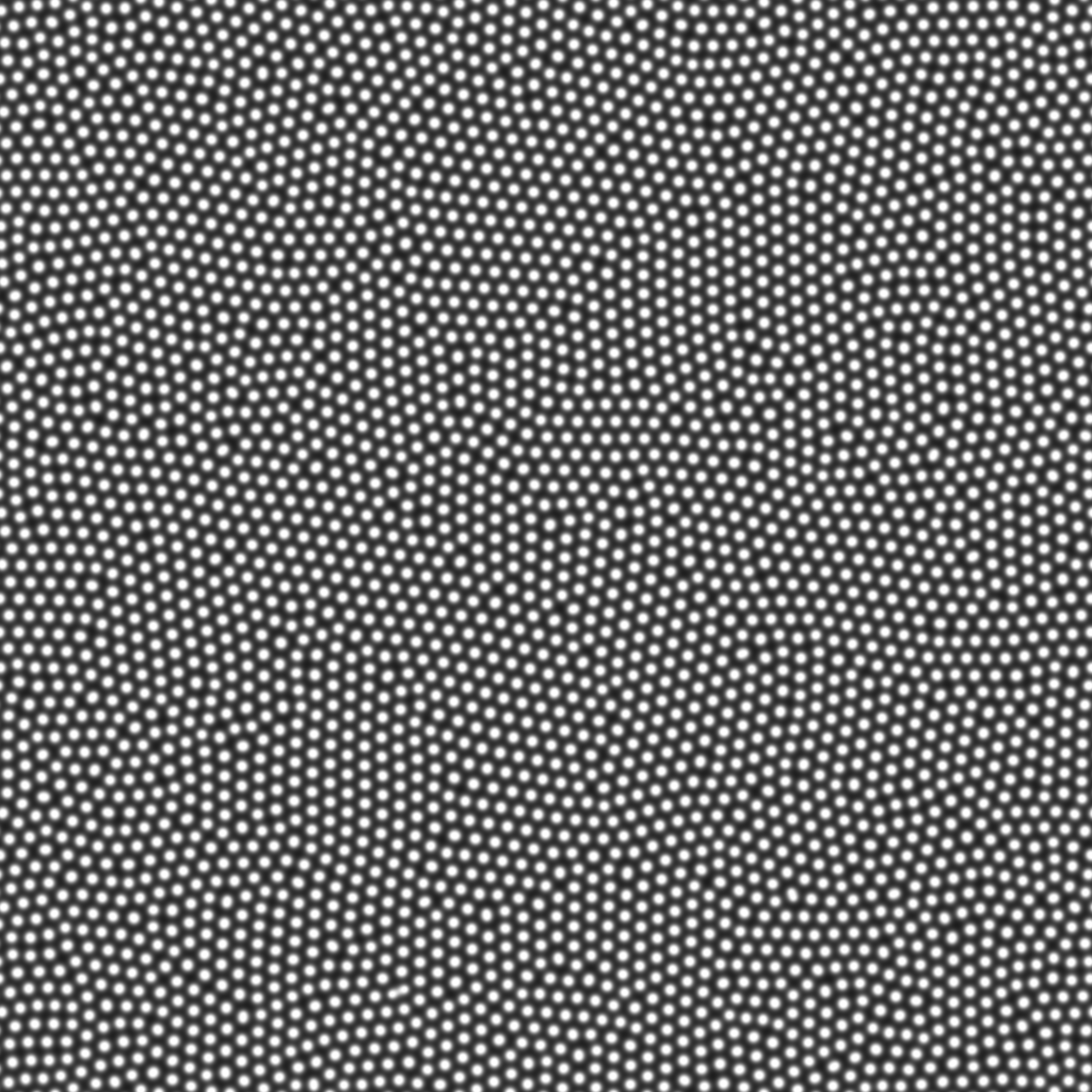
Figure 5.5: Crushed pattern
Feed:0.0263 / Kill:0.06
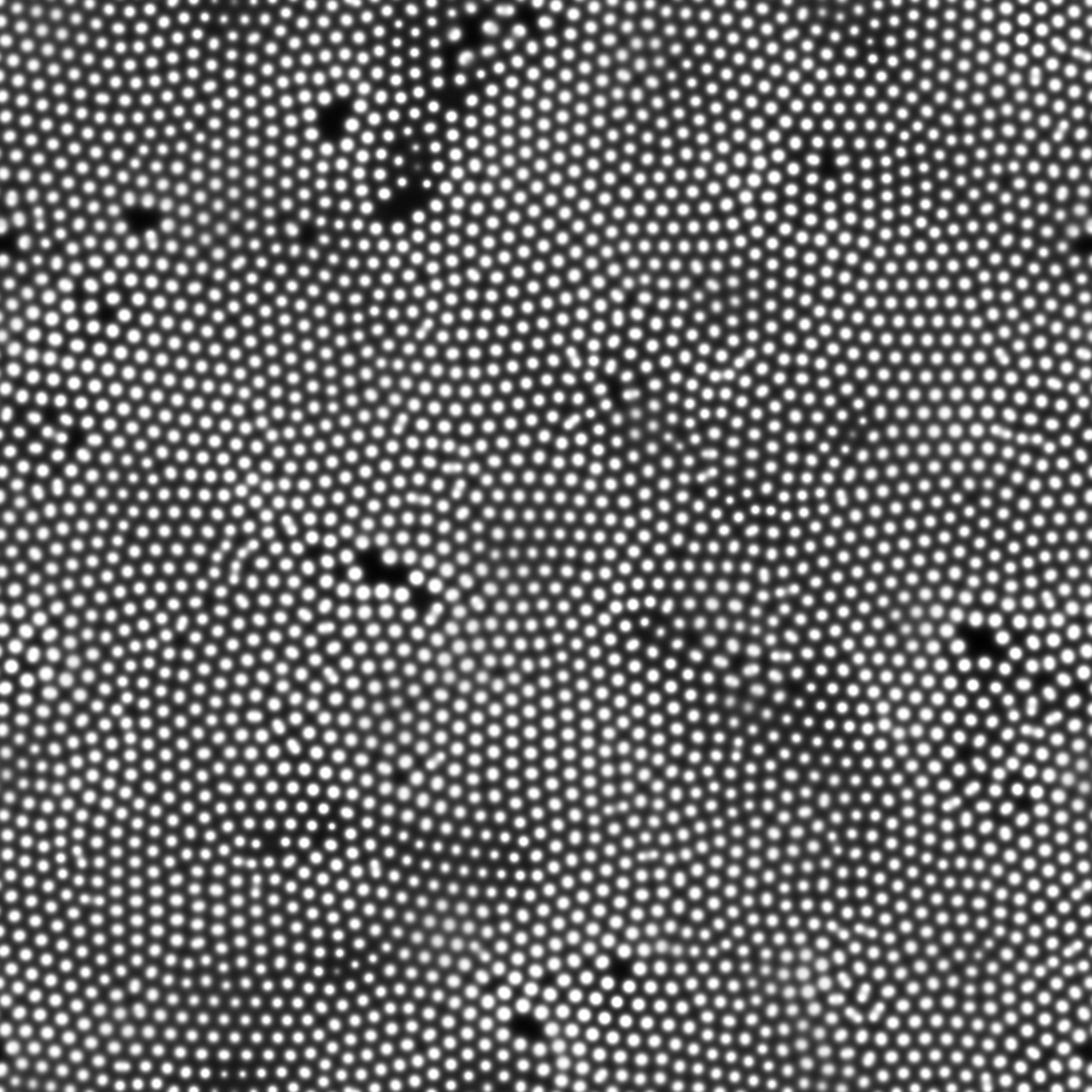
Figure 5.6: Crushing seems to repeat disappearance and division
Feed:0.077 / Kill:0.0615
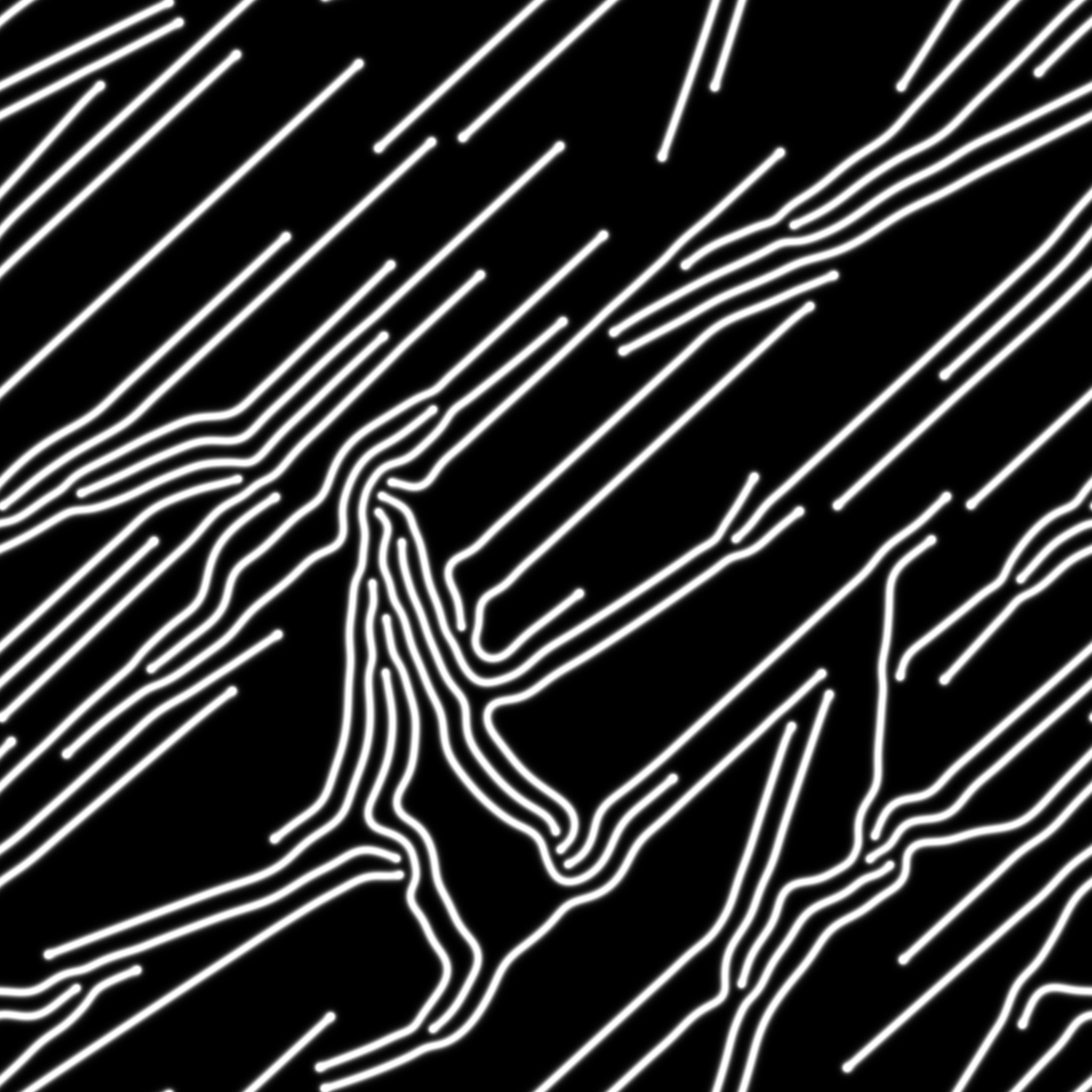
Figure 5.7: A pattern that stretches straight and avoids collision
Feed:0.039 / Kill:0.058
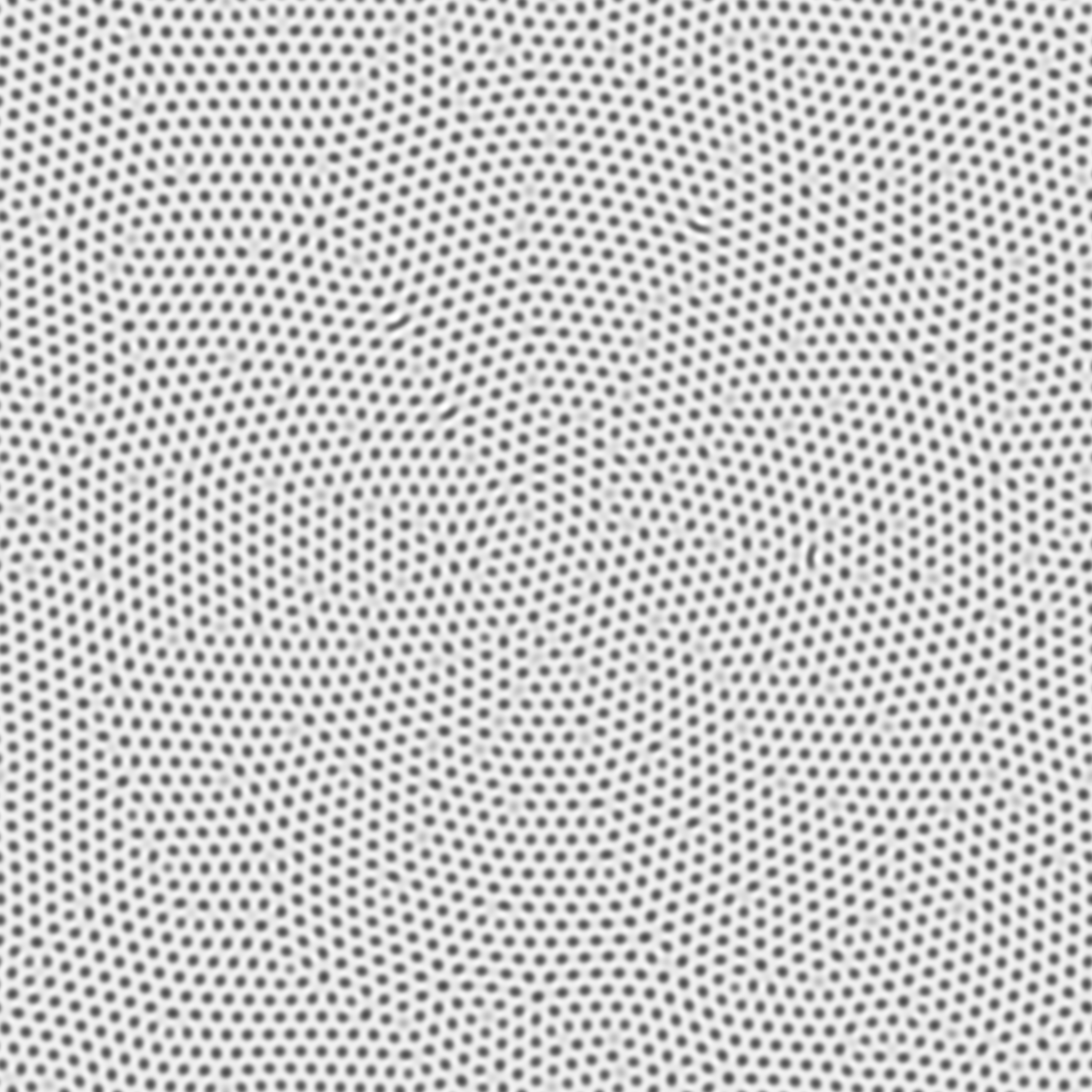
Figure 5.8: Plump hole pattern
Feed:0.026 / Kill:0.051
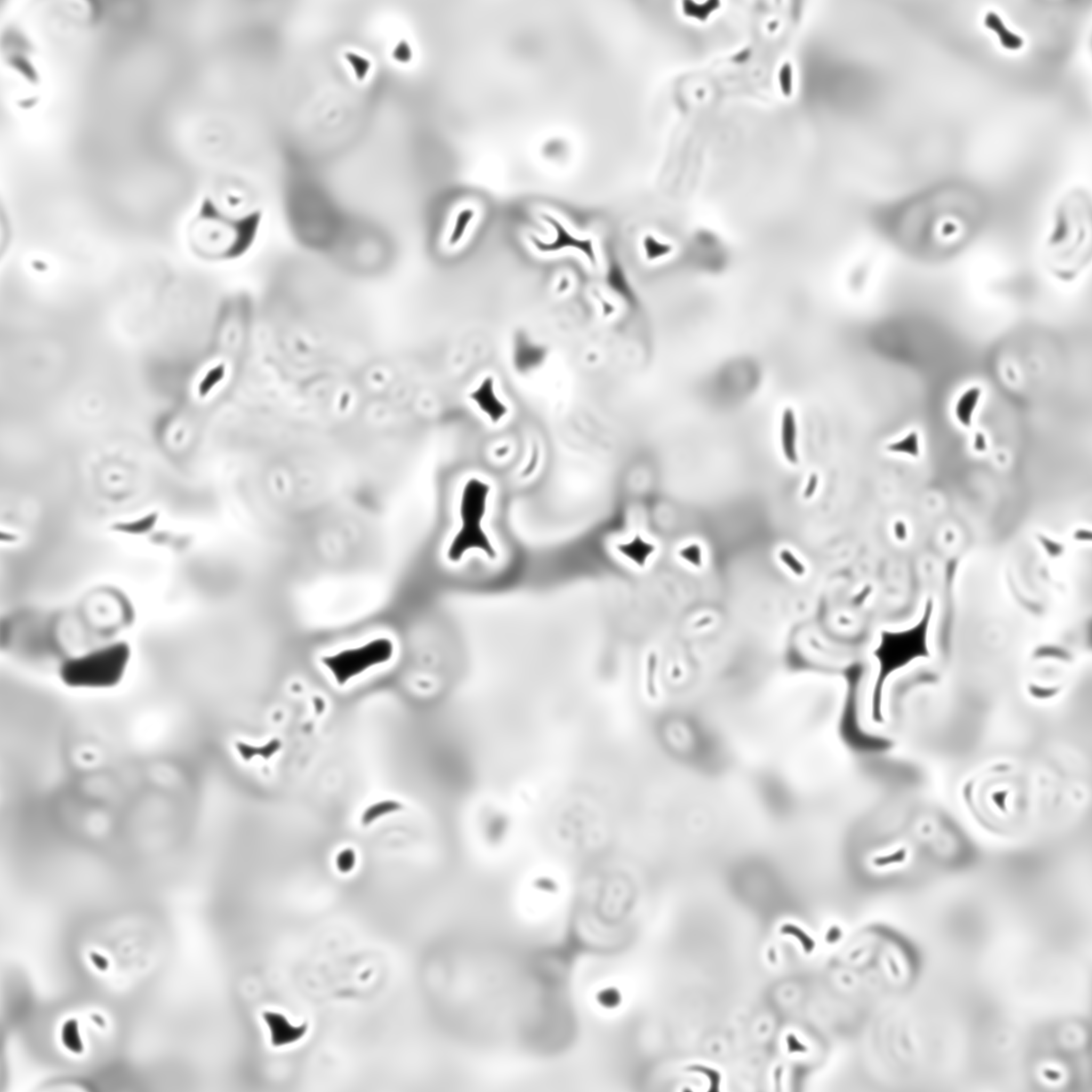
Figure 5.9: It seems that it is always undulating and unstable
Feed:0.014 / Kill:0.0477
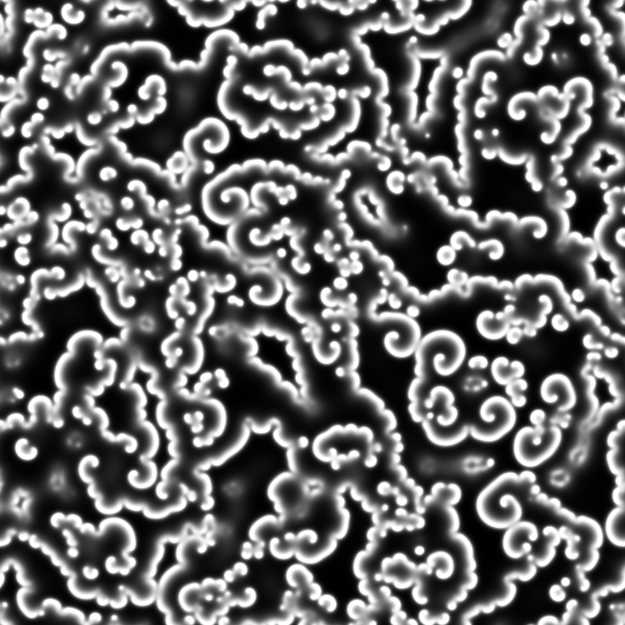
Figure 5.10: Pattern that continues to spread like ripples
Here, I will introduce a sample that expresses the beautiful texture unique to Unity using Surface Shader. The sample scene whose operation can be confirmed is ReactionDiffusion2D_2 .
The process of ReactionDiffusion itself is the same as the normal version, but when creating the texture for drawing, a normal map is also created to give a three-dimensional effect. Also, the resulting texture was RenderTextureFormat.RFloat, but since the normal map stores the normal vector in the XYZ directions, it is created with RenderTextureFormat.ARGBFloat.
ReactionDiffusion2DForStandard.cs
void Initialize()
{
  ...
  heightMapTexture = CreateRenderTexture(texWidth, texHeight,
    RenderTextureFormat.RFloat); // Create texture for height map
  normalMapTexture = CreateRenderTexture(texWidth, texHeight,
    RenderTextureFormat.ARGBFloat); // Create texture for normal map map
  ...
}

/// <summary>
/// Create RenderTexture
/// </summary>
/// <param name="width"></param>
/// <param name="height"></param>
/// <param name="texFormat"></param>
/// <returns></returns>
RenderTexture CreateRenderTexture(
  int width,
  int height,
  RenderTextureFormat texFormat)
{
    RenderTexture tex = new RenderTexture(width, height, 0,
      texFormat, RenderTextureReadWrite.Linear);
    tex.enableRandomWrite = true;
    tex.filterMode = FilterMode.Bilinear;
    tex.wrapMode = TextureWrapMode.Repeat;
    tex.Create();

    return tex;
}

...

void DrawTexture()
{
  ...
  cs.SetTexture(kernelDraw, "_HeightMap", heightMapTexture);
  cs.SetTexture (kernelDraw, "_NormalMap", normalMapTexture); // Texture set for normal map
  cs.Dispatch(kernelDraw,
    Mathf.CeilToInt((float)texWidth / THREAD_NUM_X),
    Mathf.CeilToInt((float)texHeight / THREAD_NUM_X),
    1);
}
In ComputeShader, the slope is calculated from the density difference with the surrounding grid and written to the texture for the normal map.
ReactionDiffusion2DStandard.compute
float3 GetNormal(int x, int y) {
  float3 normal = float3(0, 0, 0);
  float c = GetValue(x, y);
  normal.x = ((GetValue(x - 1, y) - c) - (GetValue(x + 1, y) - c));
  normal.y = ((GetValue(x, y - 1) - c) - (GetValue(x, y + 1) - c));
  normal.z = 1;
  normal = normalize(normal) * 0.5 + 0.5;
  return normal;
}

...

// Draw on texture
[numthreads(THREAD_NUM_X, THREAD_NUM_X, 1)]
void Draw(uint3 id : SV_DispatchThreadID)
{
  float c = GetValue(id.x, id.y);

  // height map
  _HeightMap[id.xy] = c;

  // normal map
  _NormalMap[id.xy] = float4(GetNormal(id.x, id.y), 1);
}
Pass the two created textures to the Surface Shader and draw the pattern. Surface Shader is a shader wrapped for easy use of Unity's physics-based rendering, just assign the necessary data to the SurfaceOutputStandard structure in the surf function and output it, and it will automatically light it. ..
Definition of SurfaceOutputStandard structure
struct SurfaceOutputStandard
{
    fixed3 Albedo; // Base (diffuse or specular) color
    fixed3 Normal; // normal
    half3 Emission; // Emission color
    half Metallic; // 0 = non-metal, 1 = metal
    half Smoothness; // 0 = coarse, 1 = smooth
    half Occlusion; // Occlusion (default 1)
    fixed Alpha; // Transparency alpha
};
ReactionDiffusion2DStandard.shader
void surf(Input IN, inout SurfaceOutputStandard o) {

  float2 uv = IN.uv_MainTex;

  // Get concentration
  half v0 = tex2D(_MainTex, uv).x;

  // Normal acquisition
  float3 norm = UnpackNormal(tex2D(_NormalTex, uv));

  // Get the value of the boundary between A and B
  half p = smoothstep(_Threshold, _Threshold + _Fading, v0);

  o.Albedo = lerp (_Color0.rgb, _Color1.rgb, p); // Base color
  o.Alpha = lerp (_Color0.a, _Color1.a, p); // Alpha value
  o.Smoothness = lerp (_Smoothness0, _Smoothness1, p); // Smoothness
  o.Metallic = lerp (_Metallic0, _Metallic1, p); // Metallic
  o.Normal = normalize(float3(norm.x, norm.y, 1 - _NormalStrength));  // 法線

  o.Emission = lerp (_Emit0 * _EmitInt0, _Emit1 * _EmitInt1, p) .rgb; //⁇
}
Use Unity's built-in function unpackNormal to get the normals from the normal map. In addition, various colors and textures of Surface Output Standard are set from the ratio of density difference .
When you run it, you should see something like the following.
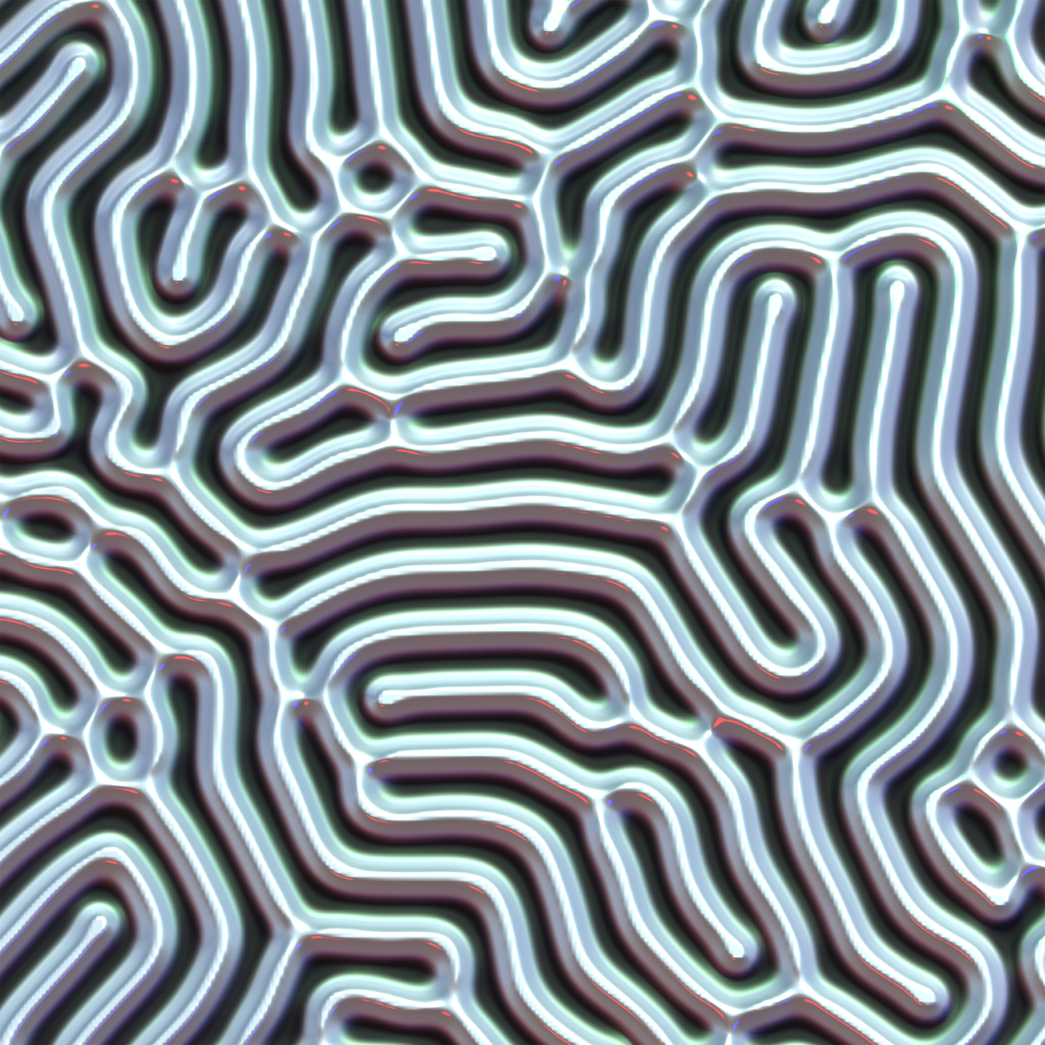
Figure 5.11: Surface Shader version
The normal map creates a three-dimensional effect. In addition, although it is not known in monochrome, the gloss of the RGB 3-color point light in the scene is also expressed.
Let's extend Reaction Diffusion, which used to be a simulation on a two-dimensional plane, to three dimensions. The basic flow is the same as for 2D, but since the dimension is increased by 1, the method of creating RenderTexture and ComputeBuffer and the method of Laplace operation are slightly different. The sample scene whose operation can be confirmed is ReactionDiffusion3D .
Some initialization processing is added to change the Render Texture to which the density difference is written from 2D to 3D.
ReactionDiffusion3D.cs
RenderTexture CreateTexture(int width, int height, int depth)
{
  RenderTexture tex = new RenderTexture(width, height, 0,
    RenderTextureFormat.RFloat, RenderTextureReadWrite.Linear);
  tex.volumeDepth = depth;
  tex.enableRandomWrite = true;
  tex.dimension = UnityEngine.Rendering.TextureDimension.Tex3D;
  tex.filterMode = FilterMode.Bilinear;
  tex.wrapMode = TextureWrapMode.Repeat;
  tex.Create();

  return tex;
}
First, put the depth in the Z direction in tex.volumeDepth. Then I put UnityEngine.Rendering.TextureDimension.Tex3D in tex.dimension. This is a setting to specify that RenderTexture is a 3D volume texture. The Render Texture is now a 3D volume texture. Similarly, the Compute Buffer that stores the Reaction Diffusion simulation results is also made three-dimensional. This simply secures the size of width x height x depth.
ReactionDiffusion3D.cs
void Initialize()
{
  ...
  int whd = texWidth * texHeight * texDepth;
  buffers = new ComputeBuffer[2];
  ...
  for (int i = 0; i < buffers.Length; i++)
  {
     buffers[i] = new ComputeBuffer(whd, Marshal.SizeOf(typeof(RDData)));
  }
  ...
}
Next is the change on the Compute Shader side. First, in order to RenderTexture for the writing of the result is a three-dimensional, ComputeShader of the side of the texture definition RWTexture2D <float> from RWTexture3D <float> will change to.
ReactionDiffusion3D.compute
RWTexture3D <float> _HeightMap; // Heightmap
Next is the three-dimensionalization of the Laplacian function. It has been changed to refer to a total of 27 squares of 3x3x3. By the way, the degree of influence of laplacePower is a value that was somehow calculated.
ReactionDiffusion3D.compute
// Surrounding index calculation table referenced by the Laplacian function
static const int3 laplaceIndex[27] = {
  int3 (-1, -1, -1), int3 (0, -1, -1), int3 (1, -1, -1),
  int3 (-1, 0, -1), int3 (0, 0, -1), int3 (1, 0, -1),
  int3 (-1, 1, -1), int3 (0, 1, -1), int3 (1, 1, -1),

  int3 (-1, -1, 0), int3 (0, -1, 0), int3 (1, -1, 0),
  int3 (-1, 0, 0), int3 (0, 0, 0), int3 (1, 0, 0),
  int3 (-1, 1, 0), int3 (0, 1, 0), int3 (1, 1, 0),

  int3 (-1, -1, 1), int3 (0, -1, 1), int3 (1, -1, 1),
  int3 (-1, 0, 1), int3 (0, 0, 1), int3 (1, 0, 1),
  int3 (-1, 1, 1), int3 (0, 1, 1), int3 (1, 1, 1),
};

// Impact of the grid around the Laplacian
static const float laplacePower[27] = {
  0.02, 0.02, 0.02,
  0.02, 0.1,  0.02,
  0.02, 0.02, 0.02,

  0.02, 0.1,  0.02,
  0.1, -1.0,  0.1,
  0.02, 0.1,  0.02,

  0.02, 0.02, 0.02,
  0.02, 0.1,  0.02,
  0.02, 0.02, 0.02
};

// Buffer index calculation
int GetIndex(int x, int y, int z) {
  x = (x < 0) ? x + _TexWidth : x;
  x = (x >= _TexWidth) ? x - _TexWidth : x;

  y = (y <0)? y + _TexHeight: y;
  y = (y> = _TexHeight)? y - _TexHeight: y;

  z = (z <0)? z + _TexDepth: z;
  z = (z> = _TexDepth)? z - _TexDepth: z;

  return z * _TexWidth * _TexHeight + y * _TexWidth + x;
}

// Laplacian function of U
float LaplaceU(int x, int y, int z) {
  float sumU = 0;

  for (int i = 0; i < 27; i++) {
    int3 pos = laplaceIndex[i];

    int idx = GetIndex(x + pos.x, y + pos.y, z + pos.z);
    sumU += _BufferRead[idx].u * laplacePower[i];
  }
  return sumU;
}

// Laplacian function of V
float LaplaceV(int x, int y, int z) {
  float sumV = 0;

  for (int i = 0; i < 27; i++) {
    int3 pos = laplaceIndex[i];
    int idx = GetIndex(x + pos.x, y + pos.y, z + pos.z);
    sumV += _BufferRead[idx].v * laplacePower[i];
  }
  return sumV;
}
Since the Render Texture of the simulation result is a 3D volume texture, even if you paste the texture on the Unlit Shader or Surface Shader as before, it will not be displayed normally. In the sample, polygons are generated and drawn using a method called the Marching cubes method, but due to space limitations, the explanation of implementation will be omitted. For an explanation of the Marching Cubes method, please refer to "Chapter 7 Introduction to the Marching Cubes Method in an Atmosphere" in Unity Graphics Programming Vol.1. Another method is to draw with volume rendering using ray marching. A very easy-to-understand implementation * 1 is introduced on Mr. Utsu's blog, so please refer to it.
[* 1] Dent Tips http://tips.hecomi.com/entry/2018/01/05/192332
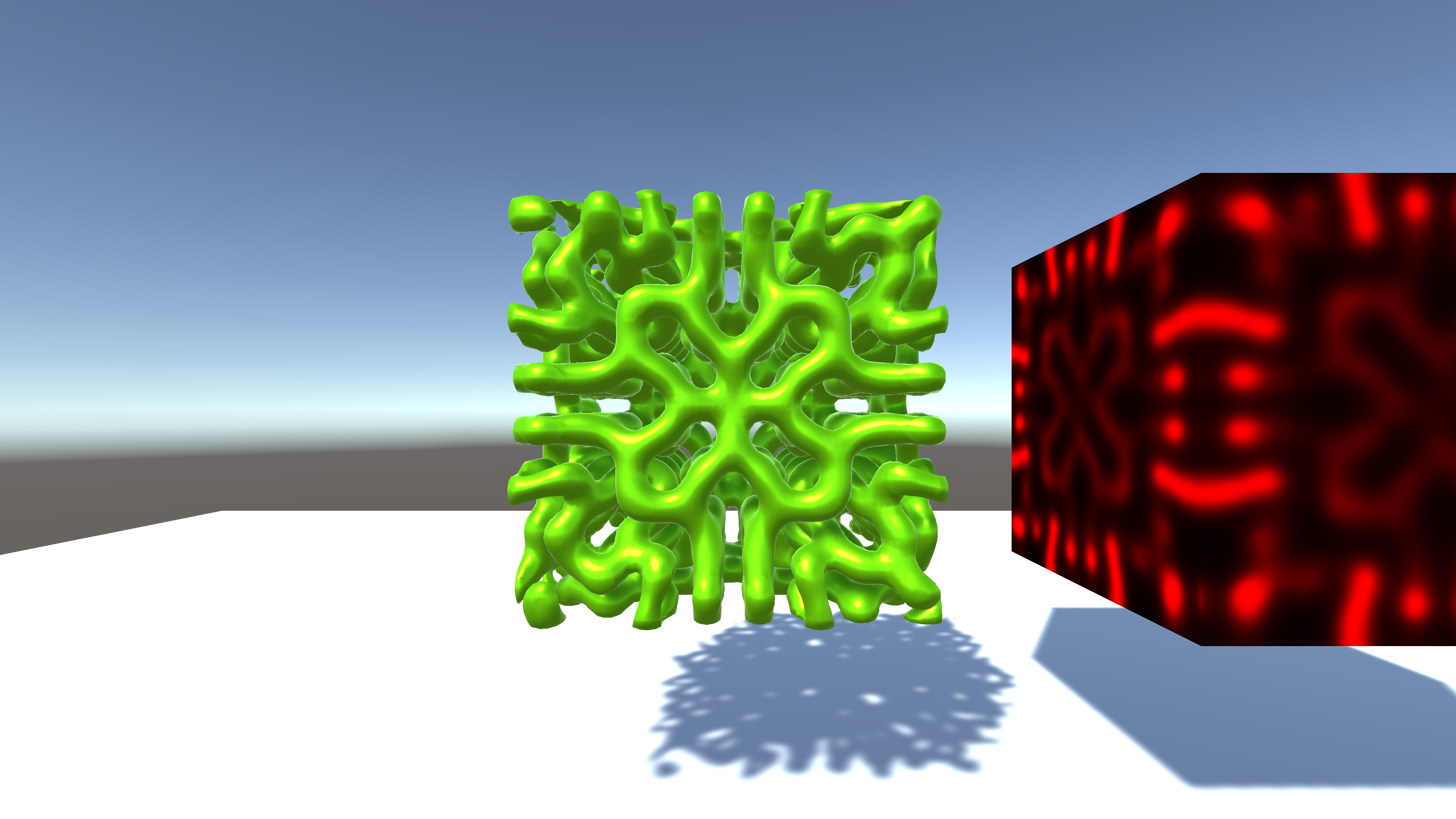
Figure 5.12: 3D Reaction Diffusion
I introduced how to make a creature-like pattern using the Gray-Scott model. You can create a completely different pattern by just changing the parameters of Feed and Kill, so be careful as the time will pass quickly if you get absorbed in it (* There are individual differences)
Also, for works using Reaction Diffusion , Nakama Kouhei's "DIFFUSION" * 2 and Kitahara Nobutaka's "Reaction-Diffusion" * 3 . Would you like to be obsessed with the mysterious charm of Reaction Diffusion?
[*2] DIFFUSION https://vimeo.com/145251635
[*3] Reaction-Diffusion https://vimeo.com/176261480